Line patrol car
Video tutorial 20 - Line patrol car: https://singtown.com/learn/50037/
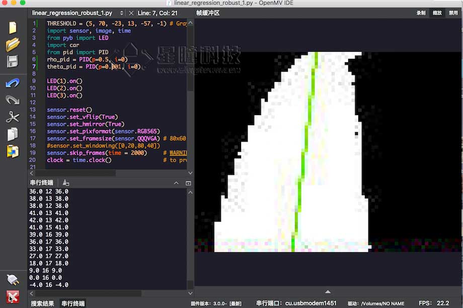
This example shows the use of the get_regression() method on the OpenMV Cam to obtain the linear regression of the ROI. Using this method, it is easy to make the robot track all lines pointing in the same general direction.
This routine can be used for robot line patrol, and the effect is very good.
Car chasing balls
Video tutorial 9 - The car that chases the ball: https://singtown.com/learn/49239/
Prepare materials
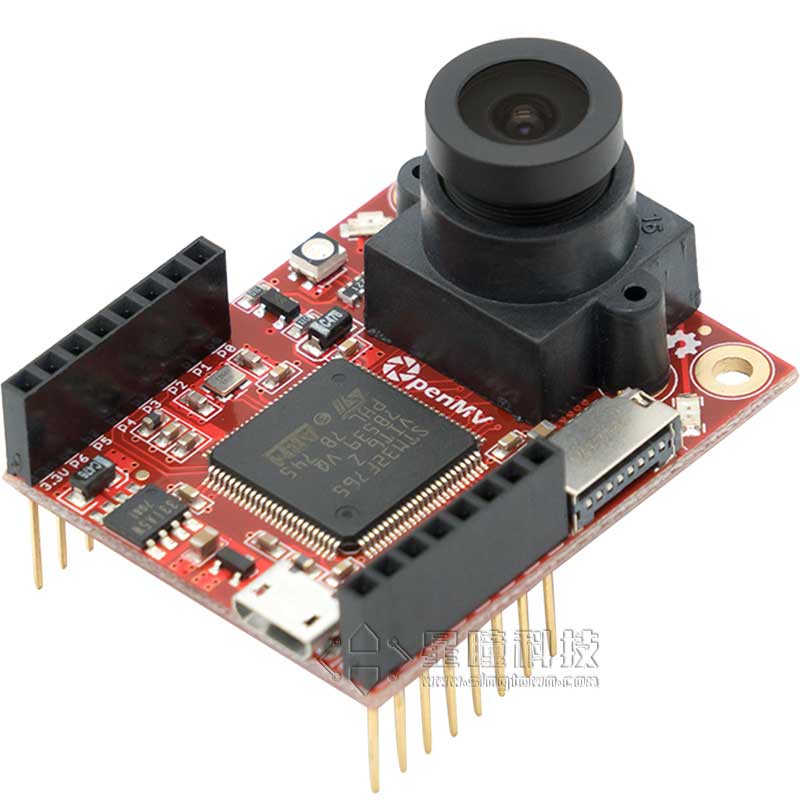
OpenMV circuit board x1:\
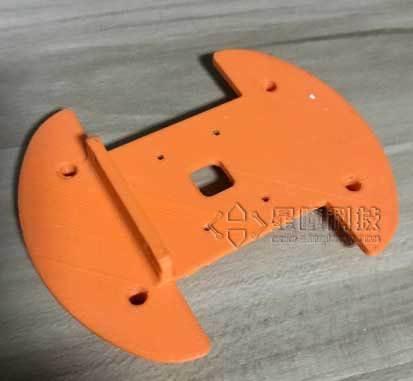
3D printed car base:
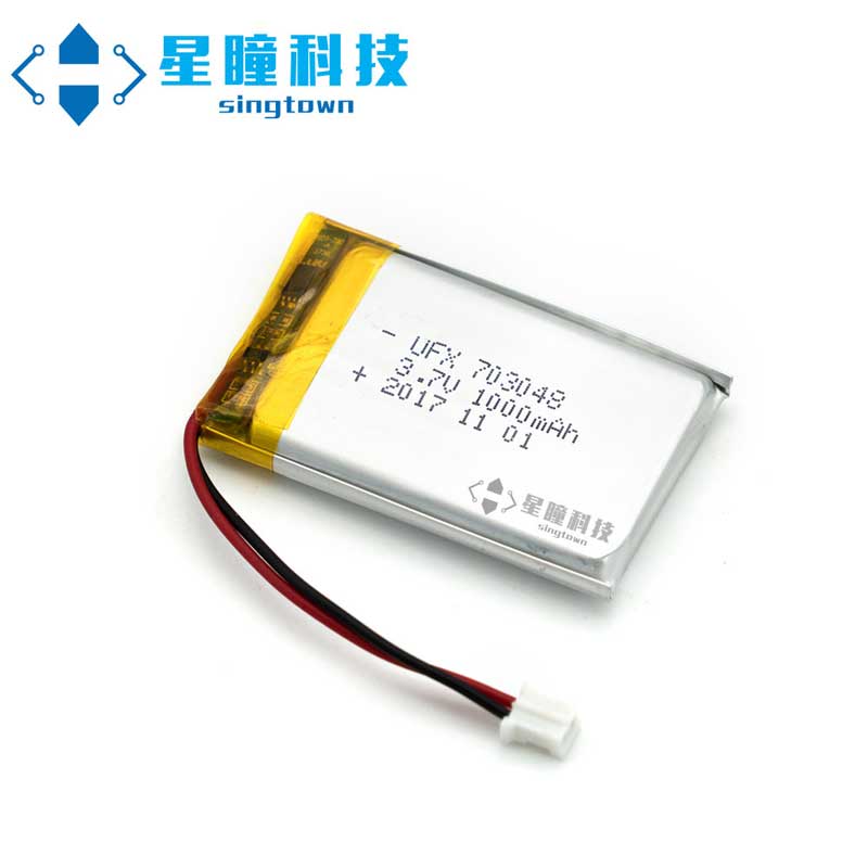
- 3.7V lithium battery x1:
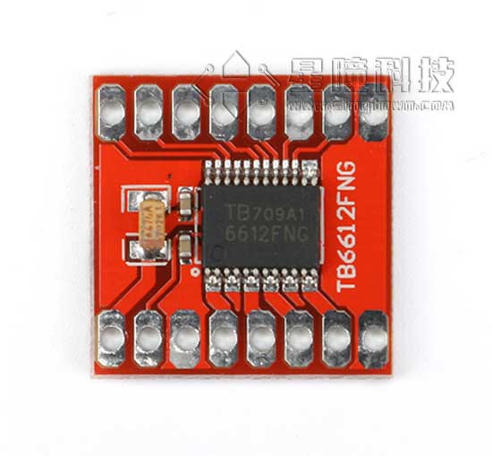
- TB6612 motor driver board x1:
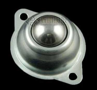
- Bull's eye wheel x2:
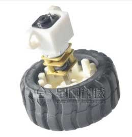
- N20 DC motor x2 (including fixed seat, including tire):
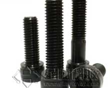
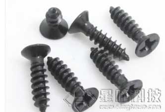
- M3*20 screw nut x2:
- M2*4 self-tapping screw x2
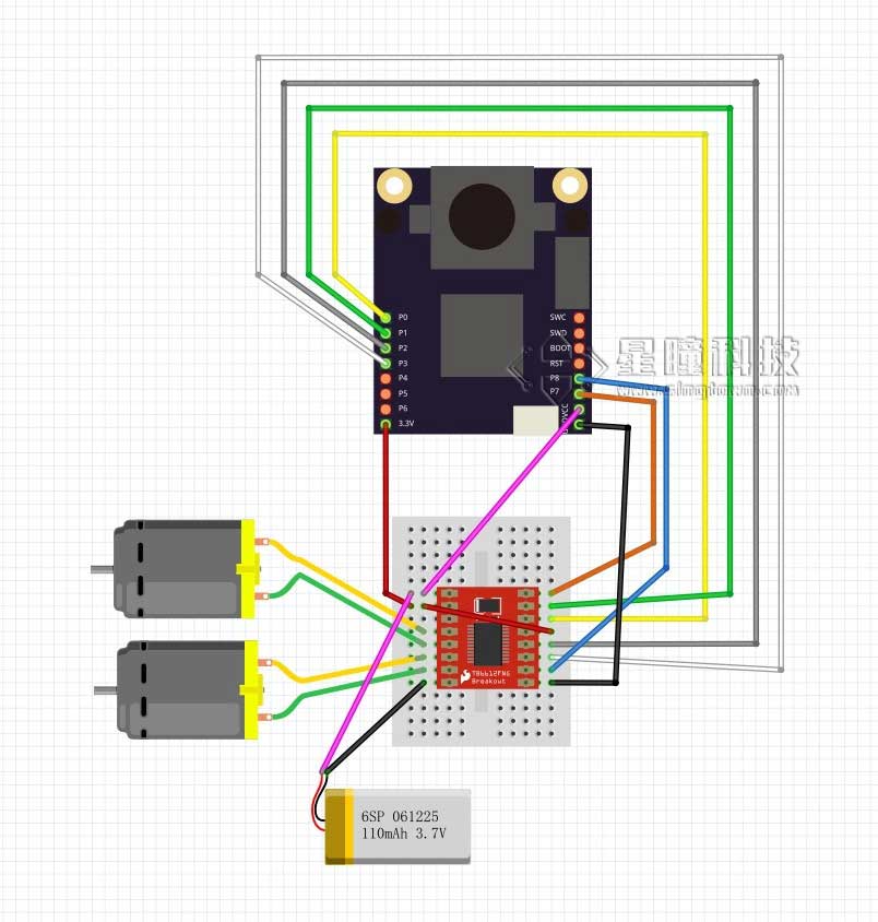
Connect the circuit and test the motor
Write the module of the car
First of all, why do we need to write a module? It is not difficult to drive the motor directly. – Because this is the best code reusability, and the control logic is independent of the structure of the car. For different cars, just change the module of the car.
car.py
from pyb import Pin, Timer
inverse_left=False  #change it to True to inverse left wheel
inverse_right=False #change it to True to inverse right wheel

ain1 =  Pin('P0', Pin.OUT_PP)
ain2 =  Pin('P1', Pin.OUT_PP)
bin1 =  Pin('P2', Pin.OUT_PP)
bin2 =  Pin('P3', Pin.OUT_PP)
ain1.low()
ain2.low()
bin1.low()
bin2.low()

pwma = Pin('P7')
pwmb = Pin('P8')
tim = Timer(4, freq=1000)
ch1 = tim.channel(1, Timer.PWM, pin=pwma)
ch2 = tim.channel(2, Timer.PWM, pin=pwmb)
ch1.pulse_width_percent(0)
ch2.pulse_width_percent(0)

def run(left_speed, right_speed):
    if inverse_left==True:
        left_speed=(-left_speed)
    if inverse_right==True:
        right_speed=(-right_speed)

    if left_speed < 0:
        ain1.low()
        ain2.high()
    else:
        ain1.high()
        ain2.low()
    ch1.pulse_width_percent(int(abs(left_speed)))

    if right_speed < 0:
        bin1.low()
        bin2.high()
    else:
        bin1.high()
        bin2.low()
    ch2.pulse_width_percent(int(abs(right_speed)))
Save the above file as car.py, and save car.py to OpenMV according to the use of the module.
Test the code in the IDE:\ main.py
import car

while True:
    car.run(100,100)
Check if the car is moving forward. If not, change inverse_left and inverse_right in the second and third lines to reverse the left or right wheel to ensure that the car is moving forward.
PID algorithm implementation
PID algorithm is a very common algorithm used in control, and there are many principles on the Internet.\ https://zh.wikipedia.org/wiki/PID控制器\ http://baike.baidu.com/link?url=-obQq78Ur4bTeqA10bIniO6y0euQFcWL9WW18vq2hA3fyHN3rt32o79F2WPE7cK0Di9M6904rlHD9ttvVTySIK\ The code is very simple. I directly copied the source code of a flight controller:\ https://github.com/wagnerc4/flight_controller/blob/master/pid.py\ It is a copy of ArduPilot\ https://github.com/ArduPilot/ardupilot
pid.py
from pyb import millis
from math import pi, isnan

class PID:
    _kp = _ki = _kd = _integrator = _imax = 0
    _last_error = _last_derivative = _last_t = 0
    _RC = 1/(2 * pi * 20)
    def __init__(self, p=0, i=0, d=0, imax=0):
        self._kp = float(p)
        self._ki = float(i)
        self._kd = float(d)
        self._imax = abs(imax)
        self._last_derivative = float('nan')

    def get_pid(self, error, scaler):
        tnow = millis()
        dt = tnow - self._last_t
        output = 0
        if self._last_t == 0 or dt > 1000:
            dt = 0
            self.reset_I()
        self._last_t = tnow
        delta_time = float(dt) / float(1000)
        output += error * self._kp
        if abs(self._kd) > 0 and dt > 0:
            if isnan(self._last_derivative):
                derivative = 0
                self._last_derivative = 0
            else:
                derivative = (error - self._last_error) / delta_time
            derivative = self._last_derivative + \
                                     ((delta_time / (self._RC + delta_time)) * \
                                        (derivative - self._last_derivative))
            self._last_error = error
            self._last_derivative = derivative
            output += self._kd * derivative
        output *= scaler
        if abs(self._ki) > 0 and dt > 0:
            self._integrator += (error * self._ki) * scaler * delta_time
            if self._integrator < -self._imax: self._integrator = -self._imax
            elif self._integrator > self._imax: self._integrator = self._imax
            output += self._integrator
        return output
    def reset_I(self):
        self._integrator = 0
        self._last_derivative = float('nan')
Also save pid.py to OpenMV according to the use of the module.
Adjust parameters to achieve following
The main thing is to adjust the two parameters of PI, http://blog.csdn.net/zyboy2000/article/details/9418257
THRESHOLD = (5, 70, -23, 15, -57, 0) # Grayscale threshold for dark things...
import csi, image, time
csi0 = csi.CSI()

from pyb import LED
import car
from pid import PID
rho_pid = PID(p=0.4, i=0)
theta_pid = PID(p=0.001, i=0)

LED(1).on()
LED(2).on()
LED(3).on()

csi0.reset()
csi0.vflip(True)
csi0.hmirror(True)
csi0.pixformat(csi.RGB565)
csi0.framesize(csi.QQQVGA) # 80x60 (4,800 pixels) - O(N^2) max = 2,3040,000.
#csi0.window([0,20,80,40])
csi0.snapshot(time = 2000)     # WARNING: If you use QQVGA it may take seconds
clock = time.clock()                # to process a frame sometimes.

while(True):
    clock.tick()
    img = csi0.snapshot().binary([THRESHOLD])
    line = img.get_regression([(100,100)], robust = True)
    if (line):
        rho_err = abs(line.rho)-img.width()/2
        if line.theta>90:
            theta_err = line.theta-180
        else:
            theta_err = line.theta
        img.draw_line(line, color = 127)
        print(rho_err,line.magnitude,rho_err)
        if line.magnitude>8:
            #if -40<b_err<40 and -30<t_err<30:
            rho_output = rho_pid.get_pid(rho_err,1)
            theta_output = theta_pid.get_pid(theta_err,1)
            output = rho_output+theta_output
            car.run(50+output, 50-output)
        else:
            car.run(0,0)
    else:
        car.run(50,-50)
        pass
    #print(clock.fps())
If you want to make a line patrol car, just use the theta return value and rho of the line object obtained by this program (theta represents the angle of the returned line segment, rho represents the offset distance), and use theta and rho to control the angle of the car.
Rho is more important. If you don't use theta, you can just use rho.
Running effect diagram: